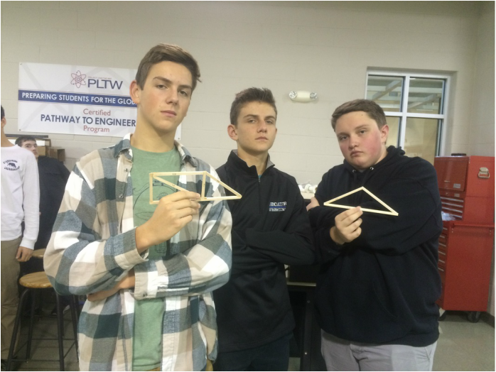
Team Picture with our trusses.
Brief Explanation
This week Kevin, David, and I were given the task to build and test 2 different trusses. Truss 1 is the one on the right, which is just a triangle. Truss 2 on the left is a triangle with a rectangle and a beam in the middle of it. We were given two days to build them. Once they were finished, we had to test how much force (Newtons) it would hold until it broke.
Truss 1 Sketch


Truss 2 Sketch


LoggerPro Graph


Video of Testing
| Truss 1 Video |
| Truss 2 Video |
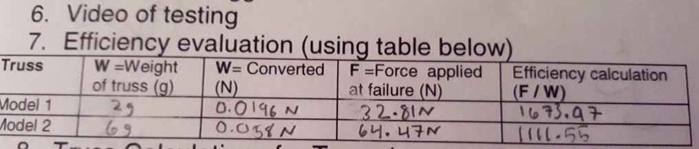
Efficiency Evaluation
Truss Calculations for Truss 1

Truss Calculations for Truss 2
Conculsion Questions
A. Explain why you think failure occurred at the truss member where it did. Did your truss fail at the member where your calculations revealed as undergoing the most stress? Yes, they did. They broke where the angles were the most obtuse. Also, they broke where the actual force was being applied. They didn't break anywhere else.
B. If given a chance to redesign your truss after testing, what changes would you make?
I would personally add more glue to each of the joints on our trusses, because it seems they didn't really break as much as they just separated. If we had just added more glue to the joints, I believe they would have actually broken, and not just had the glue separate.
