
Project Overview
The purpose of the circuit I designed in this project was to display my date of birth on a seven segment display as you switch different switches. Instead of using only AOI logic, I implemented two NOR gates into my design. Finally, this project was designed to increase our knowledge of bread boarding and wiring circuits using different chips.
Truth Table
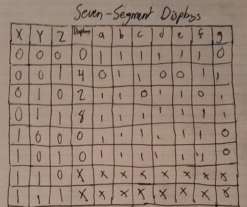
The truth table we used for this project is much different than past truth tables we've used. Totaling 11 columns and 9 rows, this truth table displays the three main inputs, and the required output for each number to be displayed correctly on the seven segment display. Each letter (a-g) represents one of the segments of the seven segment displays, so each number is composed of 7 different binary display values. The x's at the bottom of the truth table mean that it doesn't matter whatever that value ends up being.
K-maps and Simplified Logic
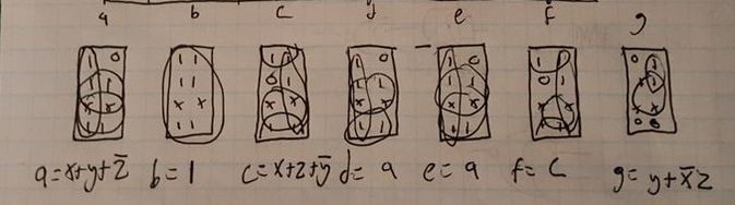
Our class learned how to use k mapping as a simple way to create functions for certain outputs for seven segment displays so that we can get the correct display when the correct switches are triggered. K-Mapping works in groups and eliminates the need for other forms of math to find the logic expression. It works by grouping the numbers together in groups of 2, 4, or 8, then reading the values of the side of the k maps. We used k mapping instead of boolean algebra because we had 7 different expressions that had to be done, so it was much more simple to just k map. The reason so many different expressions are necessary is because each segment on the display needs an expression
MultiSim
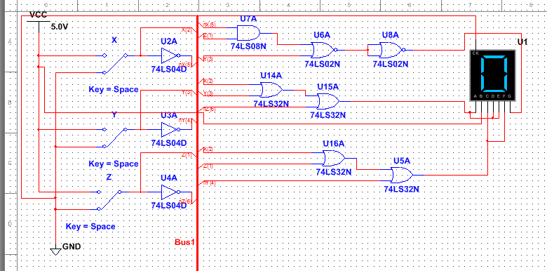
This was my MultiSim representation of my circuit. It is made with switches similar to the ones on the circuit board, the same number of gates, and the same Common Cathode Seven Segment Display. The circuit is in bus form to simplify wiring and clean up the look and organization of the simulation. For this circuit, I would need 3 inverter gates, 1 AND gate, 4 OR gates, and 2 NOR gates to complete it. 4 chips in total would be required; 1 AND, 1 Inverter, 1 OR, and 1 NOR. I used the NOR gate so I didn't have to add an extra OR gate and an extra NAND gate to meet the project requirements. Being able to use NAND and NOR gates to replace AOI gates when they're not available is very useful in many situations. These different chips can help make circuits much more simple and efficient. Seven segment displays work by receiving 7 different binary inputs into one display system. There are two types of display segments: common anodes and common cathodes. Common cathodes require a binary value of 1 to light up a segment, because cathodes are grounded automatically.
Bill of Materials
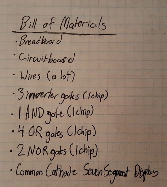
This is my Bill of Materials for my date of birth circuit. Only one of the breadboards, circuit boards, and seven segment displays were needed.
Bread-Boarding
For my second bread boarding experience, I believe it went fairly well. I had some trouble in the beginning with organizing my wires, but eventually I got the hang of it and didn't have any troubles after. One of the mistakes I made was accidentally missing one of my NOR gate connections at first, but after some quick spotting, I quickly fixed that problem and my circuit worked as intended.


Conclusion
Throughout this project, I learned how to simplify your circuits and use less wires by hooking up some pins directly from outputs to inputs. Next time, I would make sure I have the simplest expression before I begin to set up my circuit and create unnecessary minterms. I don't have many questions left with the project, I understand what I am doing with this topic now. K mapping is a very useful process in engineering and computer science. This process allows you to find the minterms for a seven segment display without needing to use any other forms of math first.
