
Project Description
For this project, my classmates and I were tasked to design a circuit that would detect a jam in a copier machine. The design was to include an LED that would not turn off until the jam was cleared, and a buzzer that wouldn't turn off until a clear button is pushed.
Constraints:
Some constraints we faced during this project were acquiring all of the random parts such as the LED's, buzzer, and motors within the physical circuit. Also. you had incorporate combinational logic into the circuit.
Constraints:
Some constraints we faced during this project were acquiring all of the random parts such as the LED's, buzzer, and motors within the physical circuit. Also. you had incorporate combinational logic into the circuit.
Algebra/KMap

|

|
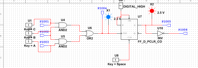
Circuits
Combinational Logic Circuit- Used to actually detect the jam within the copier. As the copier jams, paper gets stuck between two adjacent LED's. Since no light is coming from the jammed LED's, he light sensor is triggered, and the buzzer that is built within the circuit sounds. As this happens, the motor stops running until the copier is reset.
Flip Flops- The flip flops are used to make sure the buzzer is constantly buzzing when the copier is jammed, and will only stop once it is cleared.
LED and Buzzer- Once a jam is detected, the LED and buzzer will go off at the same time. The difference is, the LED will turn off when the copier is still jammed, but will keep the buzzer sounding. This process will provide time for fixes that will need to be made to the copier in order to get the machine to start working again.
Conclusion
This project has been very different from all of our previous projects involving circuits. First of all, this project did not require nearly as much thought/time to design a working circuit model. We also were supposed to set up a real life machine that would demonstrate our circuits that used moving parts, unlike before when we would only mess with LED's and such, but they did not end up working for anyone. One of the last major differences with this project was that we had to have a buzzer that would start sounding when the jam was detected, and would not stop sounding until a clear button was pushed. Overall, this was a relatively simple project that required us to use our knowledge of combinational logic circuits to have a good outcome.
