Project Overview
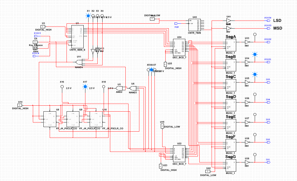
For this project, we had to create a timer that was very similar to the counter we made in the DMV project. Like the DMV counter, this was composed of two seven segment displays with different counters, features a clear switch, and is composed of 74LS163's and J/K flip flops. The counter counts to 59 and resets to 00.
Conclusion
For this project, I tried to keep my circuit from the DMV project and modify that, since it seemed easier than restarting. However, I ended up getting confused in the PLD multisim circuit, and eventually just started from scratch. I followed the same process as I did before, only modifying the wiring a bit to get it to work with the different components required, and changing the tens counter to stop at 6 and reset to 0 before 6 was displayed. Also, this counter is designed using synchronous counters, unlike the DMV project which was asynchronous. The difference between synchronous and asynchronous is that synchronous is controlled using one singular clock that is hooked up to all the different flip flops, unlike asynchronous counters which only hook the clock up to the first only. Also for this project, we used 74LS163 MSI gates instead of the 74LS193. The 163 is a 4 bit UP counter with a preloadable start, synchronous load and clear, and will show the detected value of the circuit. The 193 is a 4 bit UP or DOWN counter with a preloadable start, asynchronous load and clear, and will NOT show the detected value of the circuit. I believe my classmates could've very easily done different things for this project. There was a classwide debate on whether or not we should count from 0-59 or 1-60, which I'm sure influenced variation in each others circuits.
Design Process (Conclusion)
To design this circuit, I thought it was easiest to break it in parts. First, I decided to make the ones circuit first, using the 74LS163's. I first made it start at zero and detect nine so that would be the number it would reset at. Since I used a 74LS163, the counter ended with the number I made it detect instead of the number before. Next, I created my tens place counter using negative edge triggered J/K flip flops. Since the last number we wanted for this circuit was 59, the tens place needed to only count up to 5 so I made the circuit detect a 6. Now that they were both created, I needed to make them work together, so I got rid of the clock for the J/K and instead ran a wire from the load of the 74LS163. This would make the J/K counter go up a value every time the 74LS163 reset after 9. This made the whole circuit count from 0-59 and then reset back to 00. Now to make a button reset the counter, I needed an AND gate that would connect the two counters clear switches. The AND gate would make it so the J/K flip flop could have 2 options for resetting/clearing. Now, the counter resets when it gets to 59 or when the clear button is pressed. Once the button was on high, I ran the simulation to make sure it worked, and the probes showed me that the counter worked before I uploaded the design to my board.
